


 English
  Español
  中文简体
中文简体
Product Consultation
Your email address will not be published. Required fields are marked *
Cold Heading Agricultural Machinery Parts: A Foundation for Durability
Aug 06,2025What should you know about synchronizer guide block assembly?
Aug 06,2025Why Bus Gearbox Parts Are Critical for Vehicle Performance?
Aug 06,2025Commercial Vehicle Gearbox Parts: A Comprehensive Guide to Market Trends and Maintenance
Aug 06,2025A smooth manual transmission shift depends on several small precision components working together. One of these components is the synchronizer push block, a compact part used within certain synchronizer designs to help control the movement and loading of the synchronizing mechanism during gear engagement.
Although the component may look simple, its geometry, contact surfaces, dimensional consistency, and material properties can influence synchronization response and shift quality. For gearbox manufacturers, synchronizer suppliers, transmission rebuilders, and aftermarket distributors, understanding how a push block works is also important when evaluating wear, identifying replacement parts, or sourcing customized components.
Jiaxing OnRoll Machinery Co., Ltd. manufactures synchronizer and transmission components for automotive applications. Its synchronizer push block production combines cold heading with subsequent machining to improve production efficiency while maintaining the required mechanical characteristics of the component.
A synchronizer push block is a small component located inside or adjacent to the hub-and-sleeve mechanism of certain transmission synchronizer assemblies. Its precise position and shape vary according to the transmission and synchronizer design.
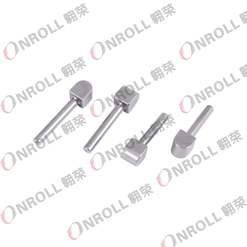
The terminology can also create confusion. Depending on the manufacturer and technical documentation, related components may be described as a synchronizer push block, key, strut, insert, slider, or guide block. These terms should not automatically be treated as interchangeable because their geometry and operating functions can differ.
A typical synchronizer assembly can include:
For parts identification, buyers should therefore avoid relying only on appearance. The transmission model, OEM reference, component dimensions, groove location, contact-face profile, and spring interface can all be necessary to confirm whether two visually similar push blocks are actually compatible.
When the driver moves the shift lever, the selector mechanism operates the shift fork, which moves the synchronizer sleeve toward the selected gear. Before the sleeve can fully engage the gear teeth, the synchronizer must reduce the speed difference between the rotating components.
The exact role of the push block depends on the synchronizer design. In many arrangements, the key, strut, or push-block mechanism helps transfer controlled axial force within the synchronizer and assists the synchronizer ring in contacting the gear cone. Friction between the ring and cone then accelerates or decelerates the components until their speeds become sufficiently close for engagement.
The simplified shift sequence is:
Shift fork → synchronizer sleeve movement → push block/key action → synchronizer ring and cone contact → speed matching → tooth engagement.
A correctly manufactured push block therefore contributes to consistent movement, preload, and synchronization timing. Excessive clearance, distorted geometry, damaged contact surfaces, or incorrect assembly can change how quickly the synchronizer responds and may increase shift effort or engagement shock.
However, poor shifting should never be attributed to the push block alone. Synchronizer rings, sleeves, hubs, springs, gears, shift forks, bearings, and transmission lubricant can produce similar symptoms.
Because the push block repeatedly contacts other synchronizer components, its working surfaces can gradually wear. Inspection is particularly important during transmission rebuilding because a damaged push block may be overlooked when attention is focused only on the synchronizer ring.
| Observed Condition | Possible Effect | What Else to Inspect |
| Polished or recessed contact surface | Changed synchronizer preload or delayed response | Ring, sleeve and spring |
| Step wear or groove formation | Restricted or inconsistent movement | Hub slot and mating surfaces |
| Chipped edge | Irregular engagement or metallic noise | Sleeve teeth and loose debris |
| Bent or distorted block | Binding and increased shift effort | Hub, fork and assembly alignment |
| Uneven wear | Asymmetric loading | Spring condition and synchronizer alignment |
Common driving symptoms may include hard shifting, delayed engagement, gear clash, abnormal resistance at the shift lever, rattling, or incomplete synchronization. These symptoms are diagnostic clues rather than proof of push-block failure.
During a rebuild, technicians should compare all push blocks in the assembly, inspect the retaining springs, check free movement within the hub slots, and measure relevant clearances according to the transmission manufacturer's service specifications.
Manufacturing method has a direct effect on production cost, dimensional repeatability, material utilization, and mechanical performance. A push block could theoretically be produced primarily through machining, but high-volume automotive production often benefits from forming the basic shape before precision finishing.
For its synchronizer push blocks, OnRoll uses a combination of cold heading and machining. The company states that this approach is intended to reduce manufacturing cost and improve efficiency while retaining the mechanical strength required by the part.
A typical production route may include:
Cold forming can provide better material utilization than machining a complete component from solid stock. It can also reduce machining time in large production runs. However, complex contact surfaces and tight functional dimensions still require controlled secondary operations, which is why combining forming and machining is particularly useful for transmission components.
There is no universal material grade, hardness value, or dimensional tolerance for every synchronizer push block. These parameters are determined by the synchronizer design, load conditions, mating components, production process, and gearbox manufacturer's drawing.
Important characteristics commonly include:
The goal is not simply to make a part that fits into the synchronizer. The component must also move correctly, maintain the intended relationship with the spring and sleeve, and remain dimensionally consistent across production batches.
Quality control may therefore involve dedicated gauges, dimensional measurement equipment, profile inspection, hardness testing when applicable, surface checks, and functional evaluation. OnRoll operates under an IATF 16949 quality management system and states that its synchronizer production includes automatic dimensional and elastic testing equipment.
For professional buyers, selecting a synchronizer push block by vehicle name alone is often insufficient. A single vehicle platform may use different transmissions across model years, engine options, markets, or drivetrain configurations.
The most useful information to provide a supplier includes:
If an OEM number is unavailable, a drawing or physical sample can be more useful than attempting to identify the component from a general gearbox photograph.
For OEM and custom projects, buyers should also evaluate whether the supplier can support the entire process from manufacturability review and tooling through sample validation and volume production. Stable batch consistency is particularly important because small dimensional changes in synchronizer components may alter assembly behavior even when individual parts appear acceptable.
Minor surface marks do not automatically mean a push block has failed, but heavily worn, chipped, distorted, or cracked components are normally better replaced than repaired.
Machining a worn push block can remove material from a functional surface and change its relationship with the spring, hub, sleeve, or synchronizer ring. Additional grinding or heat treatment may also alter the original dimensional condition. Unless an approved repair specification exists, reconditioning a small precision synchronizer component can introduce more uncertainty than using a correctly manufactured replacement.
During transmission rebuilding, replacement decisions should therefore be based on the manufacturer's wear limits and inspection criteria rather than visual appearance alone.
A synchronizer push block is small in size but demanding in production. Consistent forming, accurate functional surfaces, controlled material properties, and reliable inspection all influence how the component performs inside the synchronizer assembly.
Jiaxing OnRoll Machinery Co., Ltd. supplies automotive synchronizer and transmission components and supports customers from component development through mass production. For custom push-block projects, buyers can submit an existing sample, transmission reference, OEM number, or engineering drawing for evaluation.
Need a synchronizer push block for a new or existing gearbox program?
Contact OnRoll to discuss synchronizer push blocks and other precision car gearbox components for OEM, aftermarket, rebuilding, and transmission manufacturing applications.
Depending on the synchronizer design, the push block works with the sleeve, hub, spring, and synchronizer ring to control movement and loading during the synchronization process. It helps the assembly reach the correct condition before full gear engagement.
Possible symptoms include harder shifting, delayed engagement, abnormal shift resistance, rattling, or gear clash. These symptoms can also be caused by synchronizer rings, sleeves, hubs, forks, springs, gears, or lubrication problems, so the entire assembly should be inspected.
Not necessarily. Different manufacturers use different terminology, and the geometry and function can vary between synchronizer designs. Always identify the component using the transmission model, drawing, reference number, and dimensions.
There is no single universal specification. Material grade, hardness, heat treatment, surface condition, and tolerances should follow the gearbox or synchronizer engineering drawing.
Cold heading can produce the basic component geometry efficiently with good material utilization, while precision machining creates critical grooves, profiles, and contact surfaces. Combining the two processes can be suitable for cost-effective volume production of precision transmission components.
Ideally provide the OEM number, transmission model, 2D drawing, 3D model, material specification, critical tolerances, expected quantity, and a physical sample when available. This allows the manufacturer to evaluate manufacturability and compatibility more accurately.
Reconditioning is possible only when an approved repair specification permits it. Removing material can change functional dimensions and synchronizer preload, so damaged precision push blocks are generally safer to replace with components that meet the original design requirements.
Your email address will not be published. Required fields are marked *

(+86)-191 0581 0729
(+86)-137 5830 1558