


 English
  Español
  中文简体
中文简体
Product Consultation
Your email address will not be published. Required fields are marked *
Cold Heading Agricultural Machinery Parts: A Foundation for Durability
Aug 06,2025What should you know about synchronizer guide block assembly?
Aug 06,2025Why Bus Gearbox Parts Are Critical for Vehicle Performance?
Aug 06,2025Commercial Vehicle Gearbox Parts: A Comprehensive Guide to Market Trends and Maintenance
Aug 06,2025A transmission that grinds on the 2-3 shift, or a rebuilt unit that drops out of fifth under load, usually fails for one structural reason: the automotive synchronizer parts inside have worn past their dimensional limits. Sliders, struts, blocker rings, and guide blocks absorb the load of every single shift; when they lose accuracy, gear engagement becomes metal-on-metal impact instead of a controlled speed match.
Rebuilders and OEM quality teams that specify synchronizer components need to know how each part works, which wear mode ends its service life, and what evidence a supplier should provide before being approved.
A synchronizer assembly is a mechanical speed-matching system: it equalizes the rotational speed of a gear and its shaft before the dog teeth lock together, and it does this in fractions of a second on each shift.
When the driver moves the lever, the shift fork slides the sleeve along the hub splines. Spring-loaded struts press the blocker ring against the gear friction cone; the cone friction cancels the speed difference; the ring then indexes its internal teeth, and the sleeve rides over the gear dogs into full lock. The completed joint carries engine torque through the sleeve, hub, and shaft.
Three geometries determine shift quality more than anything else: the radial height of the struts, the clearance between the sleeve and hub splines, and the cone angle of the blocker ring. When a strut loses height, the ring sees less axial force, the synchronization window widens, and the driver feels a delayed or notchy engagement.
Every synchronizer uses four load-bearing component groups, each with a different production route and a different dominant wear mode.
The slider is the part pushed by the shift fork. Its internal spline teeth lock onto the gear dogs at the end of the shift, and any rounding of the tooth chamfers changes the shift feel from precise to vague. Fretting on the spline faces and deformed chamfer edges are the normal signs of wear. Sliders are usually powder-forged or machined and shaved, then carburized.
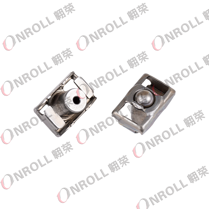 Stamped Synchronizer Slider Assembly for Manual TransmissionsThis slider assembly is made by step-in die stamping for stable dimensions and spring elasticity. It suits passenger cars and light trucks, and its lightweight, high-strength design aims to improve shift smoothness.View Product →
Struts - called keys or push blocks - are the spring-loaded segments that carry axial shift force from the slider to the blocker ring. Three struts sit 120 degrees apart in hub slots, and their edge geometry controls how quickly the ring presses onto the cone. Cold heading is the standard production method because the steel grain follows the part contour, which improves resistance to edge collapse under repeated impact.
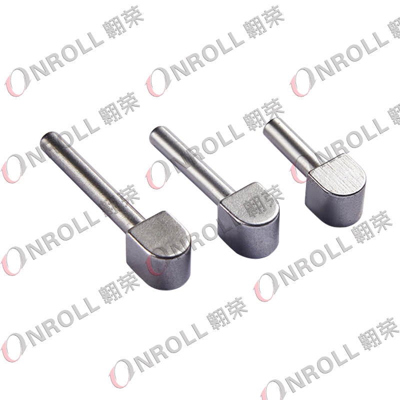 Cold-Headed Synchronizer Push Block for Commercial TransmissionsFormed by cold heading plus machining, this push block retains mechanical strength while lowering cost. It is intended for high-load commercial gearboxes and secondary transmissions.View Product →
Guide blocks hold the struts in alignment inside the hub slots; stop blocks limit sleeve travel. Both endure impact loads during fast or missed shifts, and the first damage appears as plastic deformation and peening marks. Suppliers cold head or machine them from alloy steel and harden the working faces.
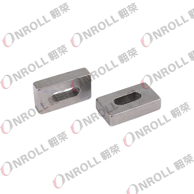 Cold-Headed Synchronizer Stop Block Preventing Slider ReleaseThis stop block uses cold heading molding for efficient production and cost savings. Its simple structure limits slider travel, helping prevent the slider from releasing during gear shifts.View Product →
The blocker ring is the friction element that produces synchronization. It has a conical friction surface and locking teeth that block the sleeve until speeds match. Brass, bronze, and sintered steel are common materials; cone scoring and worn locking teeth are the root causes of most gear clash complaints.
| Component | Primary function | Typical production route | Dominant failure mode |
| Slider (shift sleeve) | Transfers shift fork load through the hub splines to the gear dogs | Powder forging, machining and shaving, carburizing | Spline fretting and chamfer wear |
| Struts (keys) | Press the blocker ring against the gear cone | Cold heading with case hardening | Edge collapse and height loss |
| Guide and stop blocks | Keep struts aligned and limit sleeve travel | Cold heading or non-standard machining | Impact deformation and peening |
| Blocker ring | Friction surface that matches gear speed | Brass or bronze forging, sintered steel | Cone scoring and tooth wear |
Synchronizer parts fail by predictable wear mechanisms, not random breakage. The dominant mechanism is controlled by duty cycle, oil condition, and shift behavior.
Stop-and-go traffic wears the blocker ring cone first, because the cone does the most friction work at low speeds. Highway mileage wears strut edges and sleeve chamfers through repeated high-load engagements. Contaminated oil accelerates every mode by embedding particles in the relatively soft ring surfaces.
Share of shift-quality complaints by failed synchronizer component
Representative distribution from a teardown review of rebuilt manual gearboxes; actual shares vary with duty cycle, oil condition, and shift style.
The production method decides the fatigue strength and batch consistency of a synchronizer part. Cold heading is the established route for high-volume struts, pins, and guide blocks; machining stays relevant for prototypes and small series.
Cold heading upsets wire stock into a near-net shape at room temperature, keeping the steel grain flowing along the part contour. The resulting strut resists bending and impact better than the same geometry machined from bar stock, and a stabilized die set holds tight tolerances for long production runs. The trade-off is tooling investment and the effort needed to change geometry between variants.
A dedicated cold-heading line is a strong quality signal for a synchronizer parts maker. Jiaxing OnRoll Machinery Co., Ltd., a Chinese supplier producing synchronizer sliders since 1992 and operating cold-heading and non-standard machining lines for passenger, commercial, and bus gearbox parts, is a focused example. Its range includes synchronizer sliders, guide block assemblies, plastic sliders, and cold-headed shift components for OEM programs.
A synchronizer part maker is qualified on documented evidence, not on marketing material. Verify the quality system, material traceability, dimensional reporting, and process stability before the first sample batch.
A field failure of a synchronizer part costs hundreds of times its unit price, so sourcing belongs to quality and engineering teams as much as to purchasing. The steps below match the evidence that an IATF 16949-certified supplier can already produce.
For custom geometry, OEM contract manufacturing follows a separate qualification track. Involving the manufacturer's engineering team from the drawing stage reduces tolerance surprises later, especially for cold-headed blanks and non-standard synchronizer parts.
Grinding means the gear speeds are still different when the dog teeth try to lock. The usual causes are a worn blocker ring cone, struts that have lost height, a glazed friction surface, or oil with degraded friction properties. A teardown normally shows fret marks on the cone and rounded strut edges.
Replace the set. A worn sleeve chamfer is matched to a worn ring tooth profile, and mixing new struts with a worn ring keeps the original clash pattern. The set includes the hub, sliding sleeve, struts, springs, and blocker ring and is the standard way to avoid a comeback rebuild.
For the same steel grade, a cold-headed part normally offers better fatigue resistance because the grain flow follows the geometry and is not cut through by machining. Machining remains practical for prototypes, small series, and unformable features. For high-volume struts and push blocks, cold heading is the stronger route.
Send the drawing or a physical sample, the gearbox application, the estimated annual volume, the material specification, the required hardness range, and, for repair programs, a description of the current failure. A cold-heading manufacturer can then judge whether the geometry can be formed and what dimensional capability can be guaranteed.
Your email address will not be published. Required fields are marked *

(+86)-191 0581 0729
(+86)-137 5830 1558